A flipping remote control shutter for a pinhole camera
Andrew Davidhazy
andpph@davidhazy.org
One of the most difficult things to do when making pinhole photographs is to open and close the pinhole at start and end of an exposure. We resort to various approaches to accomplish this. Moving a flap or a “hat” or rotating a mask, etc. but most often we worry about moving the camera or causing flare or somehow not getting it “right”. But a major limitation of these schemes is that they usually require that the photographer perform these actions manually and thus it is not possible to make self-portraits unless one is located close to the camera.
A self-timer would help but that is one function that most simple pinhole cameras do not have. I am not including in this group film or digital SLRs or other cameras that have such a device incorporated. I am referring to simple homemade or even some commercially made pinhole cameras. Typically the exposure with these is started by removing something like a piece of tape or turning a mask or lifting a flap and ending the exposure by replacing these items to the initial location where they block the light.
A friend of mine attempted to find a commercially produce simple shuttering device that he could place on his box-type pinhole camera and then remotely activating it so that he could get himself into his pinhole photographs. He did not want to include a cable leading away from the camera in the photographs. I guess he could have had a friend make the exposure but lacking friends nearby what to do?
So he asked for my assistance. After a bit of pondering the problem I decided to try to go simple and inexpensive and based my solution on a cheap radio control toy car that I could buy. I had seen such things at Radio Shack but almost any toy store would probably have such toys.
When I went to buy a car I found that this particular model was on sale for $9.75 – full price would have been $ 12.95 – and I bought it. It was a New Bright full function RC Jeep model.
My thought was that I could do something with the wheels and forward/reverse control and attachment of a mask to the wheel that would move it left / right in front to the pinhole aperture.
The first thing was dismantling it for the part of interest. The receiver in its container and the wires leading to the motors that controlled the four functions of the vehicle. During this process I found that the torque in the rear wheels was significant and the left right assembly seemed clunky and overly complex. I then tested the motors while removed from their places on the chassis and found that they were high speed but could relatively easily be stopped without apparent damage to them. I suspect that when stopped this way the current draw probably went up but I thought that over a short time this would not be a problem and discarded some more extraneous components and ended up with the RC receiver and two identical motors. I only used one of course.
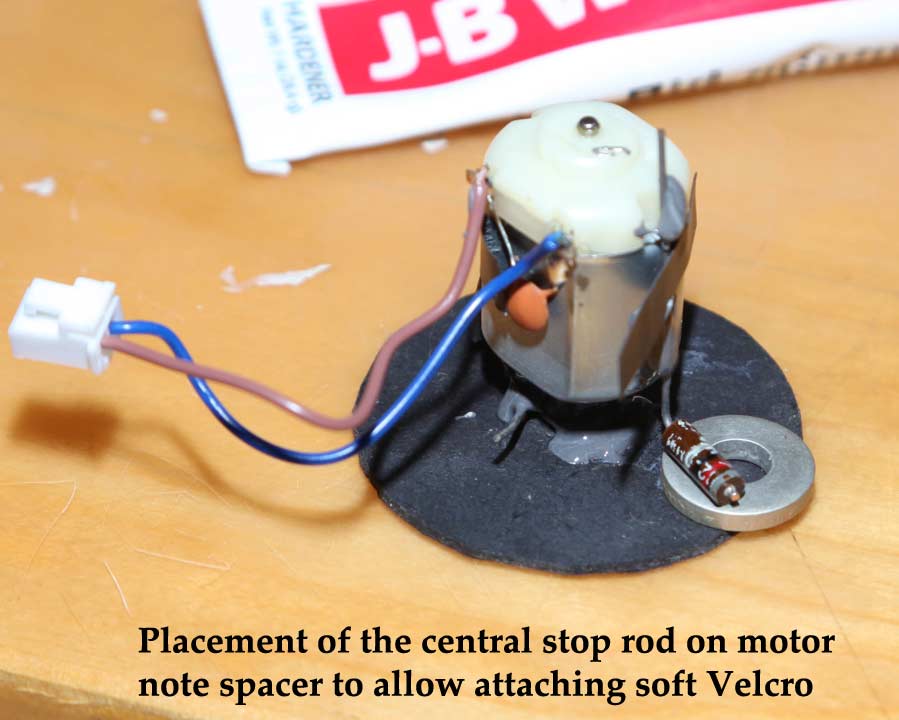
The plan was to attach a mask to the shaft of the motor and have it rotate it away and toward the pinhole. In one position it would cover the pinhole and the other it would be away from it. The illustrations show how the motor was installed with a wire twisted around its gear into a “Y” shaped fork. In front of this went a 2 inch cardboard disk. The wire and disk were glued to the drive gear at the end of the motor shaft with high strength JB Weld 2 part epoxy material. This takes 12 hours or so to dry but the bond is very strong.
At this time I thought that maybe instead of keeping the motor ON for the duration of the exposure it might be efficient to simply have the motor on to turn the mask (or capping shutter) away from the pinhole and then reverse its rotation direction to bring the mask back to its original position. With this in mind I decided to add a method to include some drag at the back of the disk. This turned out to be a resistor bent with wire bent at one end to 90 degrees and glued to the side of the motor just slightly above the surface of the disk. The idea was that I would attach some material to this to reach the disk and cause drag. I ended up using the soft part of a velcro pair attached with its adhesive back to the resistor body. I could increase or decrease drag by how firmly the resistor was bent against the back of the disk.
The Y shaped fork was aligned so that a stiff wire glued to the motor body would stop the motor turning once it had turned so far that one of the “tines” got to it and this rod would perform the same function when the other tine of the fork would get to it when the motor turned in the opposite direction.
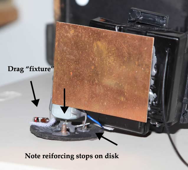
It turned out that the wire I used for the Y was a bit thin (found this out after operating the disk several times and finding that the angle of operation got bigger with every action) so eventually I had to install more substantial “stops” on the disk. I used short, stubby, flat head, bolts glued in place with epoxy as well.
Once the motor was assembled I decided to make this a “unified” construction. I could have chosen to separate the motor from the receiver but went the other way. I found a piece of printed circuit board that I had lying around and the receiver and motor were both glued to that board.
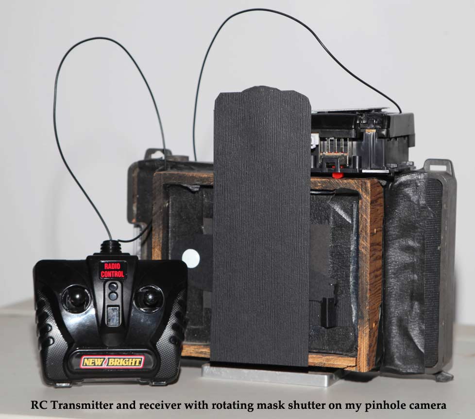
Once this gluing step was completed I placed it on top of my pinhole camera and attached a mask made of light card or heavy paper stock to the disk with two-sided Scotch tape. The idea was not to make the attachment permanent because that would create storage and transportation problems. The mask was attached so that it hung vertically (and covering the pinhole) when one tines of the Y fork was touching the “stop rod”. This would allow the mask to flip to one side until the other tine touched the rod. I used an angle of about 90 degrees for the separation of the two tines of the Y fork.
I used the connection from the receiver that was the output of the left/right lever on the transmitter. With no power to the motor the mask covered the pinhole. Effectively it acted as a "capping" shutter. When the left/right control lever was moved in one direction but the mask did not move it meant the “stop” had effectively stopped the mask from turning. Then, when the lever was moved in the opposite direction the mask, as expected (and hoped for) it turned about 90 degrees from vertical and stayed there even with power removed. This saves battery drain especially if the exposure is a long one. This was (according to plan) somewhat a function of the “drag” strip that kept some pressure on the disk as the mask swung from center to one side. Then, moving the lever in the opposite direction caused the mask to rotate back to its original position. The interval between these two actions obviously is the exposure time duration.
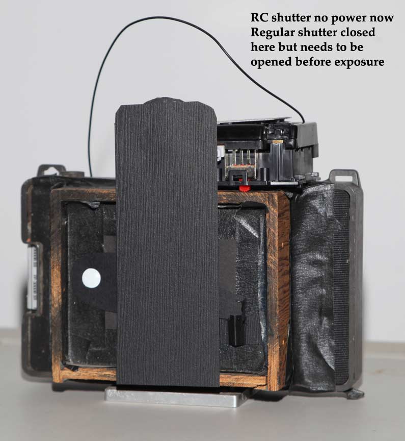
I should mention that this shutter is a secondary or capping shutter. This means that the primary shutter of the camera needs to be opened first. Then this secondary shutter can do its thing and finally the primary shutter is used after an exposure to cover up the pinhole for “standard” use.
While this device could be the permanent shutter of a pinhole camera it really functions most appropriately as a secondary shutter that is adaptable to a variety of cameras which may have a variety of distances form pinhole to mounting surface. Since the moving mask can be made of different lengths it can easily deal with boxes for 4x5, 5x7, 8x10 or other odd sizes and shapes.
Once all assembled I took a picture of myself sitting in front to the camera. As you can see my arms are at my side which indicates the exposure was not controlled by hand – although I could have quickly opened shutter, lowered hand and then quickly raised it to stop the exposure. But you will have to take my word for it. That was not the case.
I have tested the operation of the unit to a distance of about 25 feet and the operation was successful each time. I am confident that this will work well as long as I remember to turn off the power to the receiver when done using it!
If you found this article of interest and/or if you have suggestions for improvement or any other comments you care to make write to me at Andrew Davidhazy, andpph@davidhazy.org or andpph@rit.edu